NEXT MONTH will see the start of the second stage in a project to install flywheel energy storage across the London Underground network. Following initial trials last October, LU expects to have a 1 MW assembly operational on its Central line by January 2002.
Results of the test programme were unveiled in London on March 2. Project Manager Roger Walton suggested that a network-wide installation could cut the metro's energy bill by £111m over 25 years. Chief Engineer Keith Beattie said LU was drawing 200MWh a day, of which between 90 and 100MWh was in the peak periods. With 380 trains carrying an average of 3 million passengers per day across the 498km network, LU currently spends £40m to £45m a year on traction power.
Energy storage offers three main benefits: reserve power at times of peak load, smoothing of voltage fluctuations on the conductor rail due to wide load swings, and reduced energy consumption by increased receptivity for regenerative braking. LU Infrastructure Systems Engineer Mike Gellatley says all three benefits have been confirmed, although the business case is primarily based on the long-term energy savings.
A typical LU train draws 10kWh, peaking at 2á3MW when accelerating, and can regenerate 7á3kWh at 3á2MW when braking. A 1MW installation could recover up to 40% of braking energy, giving a payback period of around four years at the current price of £0á06 per kWh.
Flywheel energy storage has been around for many years, but the traditional design uses heavy steel flywheels revolving at low speeds. Energy capacity is proportional to the weight and the square of the speed, leading power engineers to consider the potential for lighter high-speed units. These are now being used for voltage smoothing and power supply support in other industries.
Siemens began trials with a high-speed flywheel on the K”ln light rail network last June, and Hannover light rail operator stra has installed a low-speed Piller Powerbridge to smooth voltage fluctuations on the outer end of its Fasenkrug branch.
LU is testing a Urenco flywheel operating in the 500 to 600Hz range (up to 36000 rev/min). Urenco Power Technologies is an offshoot of British nuclear fuel supplier Urenco, and becomes a stand-alone subsidiary on April 2. Other partners in the project are the Seeboard Powerlink consortium, which has a 30-year Private Finance Initiative concession to modernise and operate LU's power supply network, and Balfour Beatty Rail Power Systems.
Seeboard Powerlink is on course with the network modernisation, and expects to close LU's ageing power station at Lots Road next year. But Operations Manager (Generation) Richard Bettany says further work is required to reduce the spiky nature of the traction load before the feed can be transferred to the National Grid. In particular, random acceleration and braking of the trains can produce swings of up to 50% in the instantaneous traction power demand.
Carbon fibre flywheel
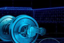
Derived from a high-speed uranium enrichment centrifuge, the Urenco flywheel has a rotor made from a carbon fibre composite, with a glass fibre core carrying a magenetised NdFeB powder coating. The stator is made from high-silicon steel laminations, with star-connected windings based on a three-phase IGBT voltage-source inverter.
A permanent-magnet DC motor-generator within the flywheel provides an all-electric interface for equal performance in charging and discharging modes. A separate electronic control module has been developed, and there is a direct connection to the DC traction supply at line voltage.
Unlike low-speed flywheels which require regular maintenance to the bearings, the Urenco units are sealed in a low vacuum to minimise drag forces, and can operate continuously with virtually no maintenance. The rotor is supported on a ball-and-cup bottom bearing, 'flying' on a thin film of oil, and held in position by a permanent magnet upper bearing.
Each flywheel is mounted within a steel case, occupying an area 600mm square and standing 1500mm high. Total weight of the assembly is 800kg. The units can be mounted within an existing substation structure, nearby, or in a remote location with a cable connection.
Since the 1960s Urenco has built and installed over 200000 centrifuges, some of which have been operating for more than 15 years. Design life for the flywheels is around 25 years. The prototype used three 100kW units, but a 200kW version is already under test at UPT's Capenhurst headquarters. The production 1MW installation would have five of these 200kW flywheels. Load sharing is fully automatic.
The flywheels are designed to 'idle' at half-charge, providing a reserve of energy to meet the draw from an accelerating train, yet leaving capacity to accept regenerated energy should a braking train enter the section. A unit left in a discharged state will gradually draw power from the line to return to the neutral position.
Model performance
For the Stage I trials, three 100kW flywheels were installed at Northfields, on a four-track section of LU's Piccadilly line. A 2á8km stretch of the Eastbound Local track between here and Acton Town can be electrically isolated for use as a test track.
With substations at both ends, and the flywheels installed at one end only, the test programme could cover all combinations of local and remote feeding, with and without the energy storage switched in. A three-car half-train of Alstom's 1996 stock from the Jubilee line was used for the trials, as the existing Piccadilly line trains do not have regenerative braking.
BBRPS undertook initial modelling to predict the performance of the system under all conditions. During October 2000 the partners conducted a week of intensive test running, collecting independent data at the flywheel, substation and on the train. There was very close correlation between the three recordings and the modelled results in each case. Furthermore, LU was able to demonstrate the repeatability of results under each set of test conditions.
After deducting auxiliary requirements, other losses and resistance/friction braking, 39% of the train's total stored energy was available for export (Fig 3). The proportion of energy recovered varied in relation to the rate of braking. 'Hard' braking at 10% g (0á8m/s2) gave little time for the flywheel to charge. 'Soft' braking at 5% g (0á4m/s2) allowed more charging time, and a greater saving.
Measuring the temperature of the train's brake resistors allowed LU to assess the amount of regenerated power not returned to the line. The resistors are designed to operate up to 650¡C, with force cooling above 350¡C. At no time did the resistors reach 300¡C, with maxima of 219¡C during hard braking trials and 45¡C in 'soft' mode. As a side benefit, Mike Gellatley expects major improvements in the passenger environment from the reduced discharge of waste heat into the confined tube tunnels.
The flywheels also demonstrated their ability to smooth voltage fluctuations. Under normal conditions, full acceleration of a train at the far end of the test track from the Acton Town substation pulled the live rail down by 180V. The flywheel reduced this drop to 100V (Fig 4). Similarly, the flywheel was able to reduce the level of overvoltage caused by regeneration. During local feeding, a 30V drop was replaced by a mean increase of 15V in the line voltage.
Stage II and beyond
LU is currently negotiating a formal project agreement for the second stage, which is expected to cost around £660000. Subject to safety case approval, this will see the existing Northfields installation reactivated in May. It will then be connected to the Piccadilly line proper, to monitor its operation in a live situation and determine whether there are any possible sources of interference. This is due to be completed by July. Even with no regenerative stock, testing will establish the value of the flywheel in smoothing voltage fluctuations.
At the same time, Urenco hopes to complete the development of the 1MW flywheel installation. The partners will also be modelling the characteristics of the Central line to determine the optimum location for the full-size test installation, which is to be in place by January 2002.
Once the live installation is able to produce sufficient data to confirm the preliminary test results, LU will be in a position to develop a business case for further installation. Roger Walton suggests it may be taken forward on a line-by-line basis, probably in conjunction with the introduction of replacement rolling stock with regenerative capability.
Given the current uncertainly over the future structure of LU under the Public-Private Parternship, Walton was unable to suggest a timescale for any future investment. Transport for London Board Member Steve Norris suggested that the potential payback profile would make flywheel installation a 'prime candidate' for some form of private finance initiative. Seeboard Powerlink's Richard Bettany confirmed that this timescale would fit well with the power consortium's existing concession, although it could equally well be taken forward as a stand-alone venture.ÊÊn
- CAPTION: The three modern fleets of tube stock on London Underground's Jubilee, Northern and Central lines are designed for regenerative braking
- CAPTION: The prototype LU installation comprised three 100 kW flywheels connected in parallel with full load sharing
- CAPTION: Fig 1. Predicted performance of the flywheels over a 90 sec trip using conventional and regenerative rolling stock
- CAPTION: Fig 2. A single-ended feeding test with minimum acceleration rates gave the longest time for the flywheels to contribute
- CAPTION: Fig 3. Analysis of the results of one test showed that around 39% of the 18 MJ total energy stored in the train was available for export through regeneration. The change in potential energy reflects the height difference between the two ends of the test track
- CAPTION: Fig 4. Demonstration of line voltage support as measured at Northfields when the test track is fed from Acton Town, showing the reduction in voltage fluctuation when the flywheel is in operation (red) compared to the normal situation (green)
- CAPTION: Fig 5. Even under the most extreme conditions, with the train cycling from full acceleration to full braking every 3 sec, the flywheel was able to follow the power demand curve