INTRO: The first of two RM900RT High Output Ballast Cleaners underwent a series of demanding checks and tests to obtain an Engineering Acceptance Certificate for use on the UK network

BYLINE: Peter Howells CEng FIMechE and Dr Bernhard Lichtberger*

BYLINE: * Peter Howells was Principal Executive Consultant, AEA Technology Rail until June 30. Dr Lichtberger is Head of Research & Testing at Plasser & Theurer Export von Bahnbaumaschinen

TWO RM900RT High Output Ballast Cleaners were ordered by Network Rail from Plasser & Theurer in 2002 and 2003. The first entered service in August 2004 on the Great Western Main Line, and the second began work on the East Coast Main Line last month. It is operated and maintained by First Swietelsky, the same joint venture that operates the machine based at Reading.

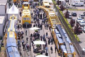
At peak performance, the RM900RT can clean ballast at a rate of 900m3/h. It is a 16-axle articulated machine consisting of two power units flanking an excavating unit and a screening wagon (above). The combined nominal power output from the two diesel engines is 1500 kW, and maximum speed when hauled in a train or under its own power is 96 km/h. Should one engine fail, the machine can be closed down using an emergency power supply, so ensuring it can leave the possession under the operator’s agreed procedures. Further details are in Table I.

The braking system meets UIC standards, with air brakes controlled by Knorr KE valves and spring-applied parking brakes. Electronic wheelslide protection and a sanding device are installed.

The individual sections are linked by bar couplings and two articulated frames. The four individual frames that form the main structure of the machine are welded assemblies of rolled steel sections and sheet steel.

The machine has two ballast screens and a high-performance excavating chain. It can add new ballast stored in up to 22 MFS hopper wagons coupled behind the machine, with conveyors on the MFS wagons moving the ballast forward for placing on the track. Similarly, spoil is loaded into separate MFS wagons in front of the ballast cleaner, the maximum again being 22.

The HOBCS is fitted with the latest electronic control technology and has a multi-channel data recorder to log the track parameters of the treated track.

The acceptance process

High Output Ballast Cleaners of this type have never been used in the UK before, and the RM900RT had to be designed and built in accordance with current Railway Group Standards. As numerous components such as the four-axle bogies are new to the UK market, Plasser & Theurer and AEA Technology Rail as Vehicle Acceptance Body took particular care to ensure that the process was carefully managed and controlled.

The requirement to ship such a large machine across Europe by rail demanded that the full acceptance process, including the various conformance tests, be carried out in Austria. With the documented results of the tests, together with ride simulations for jointed track carried out by AEA, the machine was cleared for transit through Europe and the Channel Tunnel to the UK.

Obtaining an Engineering Acceptance Certificate was achieved by applying sound engineering skills and co-operative teamwork between Plasser & Theurer and AEA Technology Rail.

Calculations

A total of 21 finite element calculations were carried out by Plasser & Theurer and scrutinised by AEA. These included calculations for the main machine frames, the bogie frames, the bogie bridge, the coupling of the excavation chain to the frame, the coupling points, and so on.

Owing to the large mass of the RM900RT, the main vehicle structures had to be mounted on four-axle bogies to meet the axleload limit.

The bridge connects a pair of two-axle bogies to form a four-axle bogie. As the bridge is mounted below the vehicle frame, the bridge is treated as a bogie for the purposes of calculation, and it must meet the relevant GM/RT2100 Issue 3 bogie structure specification.

To pass the validation process, the proof load cases for vertical loading, lifting, minor derailments and transverse forces had to be met, and six proof load cases were evaluated. The bridge also had to resist fatigue loads - 66 fatigue load cases were defined to cover all possible loading conditions: vertical weight and its dynamic effects, transverse loading caused by hunting and track cant, twisting of the bridge, braking and accelerating. Working load cases were also checked.

The finite element analysis used more than 31000 elements with a total of 182640 degrees of freedom. Shell elements were mainly used for the exact finite element model. The calculations produced stress concentrations in holes and transition zones, and example stresses for the vertical proof load are shown in Fig 1.

The excavating chain and associated rail lifting equipment is carried on the excavating wagon. Soiled ballast is removed below the sleepers by the chain and is pushed onto belt conveyors which carry it to the screening wagon. The cleaned ballast is returned to the excavating wagon and is used to fill the space below the sleepers.

For the finite element calculation of the excavating wagon the frame was represented only by shell elements. Beam and link elements were used for auxiliary purposes, mainly to attach concentrated masses. It was difficult to meet the fatigue demands of GM/RT2100 without failing the wheelset load limit and the narrow W6A loading gauge. The finite element mesh consists of 45500 elements with 266304 degrees of freedom; 11 proof loads, six fatigue load cases and six working load cases were evaluated. The fatigue evaluation was made with the post-processing software FatMel4.

X-factor test rig

To transport the ballast cleaner to Britain by rail, all approval documents and test certificates had to be obtained and checked by AEA before the trip started.

An absolute requirement for this was measurement of the X-factor, an essential element (apart from the measurement of twist) to assess the derailment safety of the machine. The X-factor describes the bogie rotation resistance and is determined by the body/bogie yaw torque and the yaw angle as the bogie is rotated beneath the vehicle with a specified constant angle speed (Fig 2). For this reason a special X-factor test rig was built in the Plasser & Theurer factory, calibrated under the supervision of AEA specialists and put into service.

Measurements

Apart from investigations into the ride and braking systems, measurements of noise and vibration, lighting, dQ/Q tests, transition resistance, tensile forces, rolling resistance and the parking brake were also carried out.

Measurements of the ride behaviour on continuously welded rail were carried out in accordance with Railway Group Standard GM/RT2141 by Plasser & Theurer’s Research & Testing Department under the supervision of AEA Technology Rail. It is an ISO9001 and EN ISO/IEC 17025 certified testing centre, recognised and certified by the Federal Railway Office (EBA) in Germany.

In addition to satisfying the supplier that the RM900RT performed as expected, the ride tests were used to gather data to validate dynamically a Vampire computer model.

To provide sufficient test data for the simulation, two measuring runs were performed with varying instrumentation. On each run 20 acceleration sensors and two precision transducers were mounted to measure spring deflections. The accelerations were built up in both the vertical and horizontal directions. Measurements were taken of the accelerations at the wagon body, at the bogie bridge of the four-axle bogies, at the bogie frame and over the axles at which the dynamic spring deflections were determined. The Dose Level was determined in the three dimensions in a separate measuring run. During these measuring runs, AEA also measured noise levels in the machines.

Braking performance was measured on Austrian Federal Railway tracks in accordance with Railway Group Standard GM/RT2042. AEA produced the test specifications and was present when the measurements were taken.

Apart from the brake path assessments in the various modes (full brake, emergency brake, quick-acting brake), the effect of the parking brake was determined by measuring the tractive force needed to move the braked vehicle.

Simulation calculations

Normally, new designs of rail vehicle for use in the UK are subjected to a series of on-track tests to prove compliance with Railway Group Standard GM/RT2141. In this instance, a derogation was granted by the Rail Safety & Standards Board which allowed on-track testing in Austria to be used to validate a vehicle model created in Vampire, AEA Technology Rail’s vehicle simulation program. The validated model was then used to predict the performance of the RM900RT over the UK Freight Acceptance Route.

With multi-vehicle modelling, a model is usually made of one vehicle and then duplicated for the number of vehicles involved. However, each of the four units of the RM900RT is unique. Because of this and the interaction between different parts of the machine, the model became the largest single Vampire model created by AEA Technology Rail.

The machine layout is accurately reproduced in the Vampire model (Fig 3), which was made in both forward and reverse running variants. Provision was also made to model the machine in working condition when it is loaded with ballast. In this condition Bogies 4 and 5 move 2m towards the front to allow a greater unloaded rail length over the excavated section. In travelling mode, these bogies are moved back to respect the minimum axle spacing in the Railway Group Standards.

Bridge 1 in Fig 3 is a levelling bridge which allows the screening wagon body to be held upright when negotiating canted track, thus ensuring that the ballast does not all move to the low side. This automatic levelling has been included in the laden model by use of the Vampire User Subroutine facility.

The bogies are to Plasser’s own design, featuring nested coil spring primary suspension with friction wedge damping. The primary suspension arrangement can be seen in the photograph above.

The secondary suspension is of the standard UIC type with a spherical centre pivot and sprung sidebearers. The connections between the bridges and the bodies are similar, but use rubber pads in the sidebearers instead of coil springs. The levelling bridge has additional roller stops outboard of the normal sidebearers with zero clearance. A 1mm gap was previously modelled, but it is not apparent on the machine as built, and removing it greatly improves the stability of the bogie.

The front power unit (ATW) is coupled to the screening wagon by a drawbar, but the other units are coupled by ball joints which support one end of the screening and excavating wagons. The dovetail sliding block for the movable bridge has been lumped in with the excavating wagon body as its freedom of movement was considered to be insignificant in the overall dynamics of the machine. Bogies 2, 3, 6 and 7 are powered, having large axle-hung hydraulic motors on both axles. The centre of gravity of these motors is outboard of the axles, giving quite a high effective unsprung mass.

In order to model all these details accurately, the Vampire model is fairly complex, and comprises 59 masses (Table II) giving the model 276 degrees of freedom. The suspension elements are shown in Table III.

Two bump stops are replaced by pin links in the laden model with the automatic levelling. The laden model also has the primary vertical spring stiffness on bogies 4 and 5 increased by 12MN/m per axlebox to represent the hydraulic rams deployed in this condition. When deployed, the rams contact the axleboxes and then move a further 10mm. The primary spring rate is 0·651MN/m per pair, or 1·302MN/m per axlebox. The rams pick up 10 x 1·302 = 13·02 kN each when deployed. With a stiffness of 12MN/m a deflection of 13·02/12 = 1·09mm will off-load the rams. This effect is modelled using bump stops. Similar principles were used to model bogie 3 in the working condition.

Torsional flexibility has been included in the four main bodies and the two span bolster bridges according to data supplied by Plasser & Theurer.

The model behaved as expected when subjected to simple static tests, but required small time steps in the analysis programs due to the large number of friction and bump stop elements.

Track data

In addition to the comprehensive vehicle model, a successful simulation also requires accurate track data. This was obtained in Austria using results from the Plasser & Theurer EM250 track recording car and used to construct a Vampire track data file of the test route from Linz to Wels-Neumarkt.

Following extensive validation to criteria included in the Method Statement forming part of the RSSB derogation, the Vampire model was run over the Vampire track data file for the UK Freight Acceptance Route. The results demonstrated that the machine met the requirements of GM/RT2141 at the design speed of 96 km/h. The model was also used to demonstrate that there were no slow speed derailment risks.

CAPTION: The RM900RT consists of four sections, with excavating and screening wagons flanked by a power unit at each end

CAPTION: Fig 1. Stress diagram for the bogie bridge

CAPTION: Fig 2. XY-diagram of an X-factor test for 1í/s mode

CAPTION: Primary suspension of the bogies

CAPTION: Fig 3. Layout of the RM 900 RT used in the Vampire model to assess dynamic riding performance

TABLE: Table I. RM900RT ballast cleaner for Network Rail

Gauge mm 1435

Overall length m 82

Weight tonnes 270

Minimum curve radius (working) m 200

Minimum curve radius (in transit) m 80

Maximum speed km/h 96

Installed power kW 1500

TABLE: Table II. Vampire model using 59 masses

Item Body Bridge Frame Wheel- Side- Motors sets bearers

Front power unit 1 - - - - -

Screening wagon 1 - - - - -

Excavating wagon 1 - - - - -

Rear power unit 1 - - - - -

Bridge 1 - 1 - - - -

Bridge 2 - 1 - - 2 -

Bridge 3 - 1 - - 2 -

Bogie 1 - - 1 2 2 -

Bogie 2 - - 1 2 2 2

Bogie 3 - - 1 2 2 2

Bogie 4 - - 1 2 2 -

Bogie 5 - - 1 2 2 -

Bogie 6 - - 1 2 2 2

Bogie 7 - - 1 2 2 2

Bogie 8 - - 1 2 2 -

Totals 4 3 8 16 20 8

TABLE: Type NPW-RT (WA4238 Axleload 207·68 kN

Bogie No Bogie 1 Wheelbase 1800mm Offset 0·2°/s left 0·310 kN

Date May 15 2004 Max angle 4·5° Offset 1·0°/s left 0·310 kN

Operator Blechinger Force 10·34 kN Offset 0·2°/s right 1·080 kN

Preset Speed 1·0í/S X-Factor 0·036 0ffset 1·0í/s right 1·080 kN

TABLE: Table III. Suspension elements in the Vampire model

Element Number

Stiffness 31

Shear springs 64

Viscous dampers 1

Friction dampers 324

Bump stops 172

Pin links 13

Bushes 11

High Output Ballast Cleaners enter service with Network Rail

The first of two RM900RT High Output Ballast Cleaners underwent a series of demanding checks and tests to obtain an Engineering Acceptance Certificate for use on the UK network. Designed to clean ballast at up to 900m??/h, the 82m long machine weighs 270 tonnes and features a number of components such as four-axle bogies that have not been used previously in the UK. Measurements taken during the acceptance process included noise and vibration levels, rolling resistance, ride quality and braking performance.

Network Rail met en service ses cribleurs de ballast à haut débit

Le premier de deux High Output Ballast Cleaners RM900RT - cribleurs de ballast à haut débit - a subi une série de vérifications et et d’essais intenses afin d’obtenir un Engineering Acceptance Certificate - certificat technique d’homologation - pour son utilisation sur le réseau du Royaume-Uni. Conçue pour nettoyer le ballast à un débit pouvant aller jusqu’à 900 m3/heure, la machine est 82m de long, pèse 270 tonnes et compte un certain nombre de composants tels que des bogies à quatre essieux qui n’ont jamais été utilisés précédemment au Royaume-Uni. Les mesures réalisées durant le processus d’homologation comprenaient les niveaux de bruit et de vibration, la résistance au roulement, la tenue de voie et les caractéristiques de freinage

Hochleistungs-Schotterreinigungs-maschine bei Network Rail

Die erste von zwei RM900RT Hochleistungs-Schotterreinigungsmaschinen passierte eine Reihe von anspruchsvollen Kontrollen und Prüfungen zur Erreichung der Zulassung für das britische Netz. Mit einer Leistung von bis zu 900m3 Schotter pro Stunde wiegt diese 82m lange Maschine 270Tonnen und zeichnet sich durch verschiedene noch nicht in Grossbritannien eingesetzte Komponenten aus, wie vierachsige Drehgestelle. Während des Zulassungsverfahren vorgenommene Messungen umfassten die Stärke von Lärm und Vibrationen, Rollwiderstand, Laufqualität und Bremsleistung

Entran en servicio las desguarneced-oras de alta capacidad de Network Rail

El primero de las dos desguarnecedoras de balasto de alta capacidad RM900RT ha pasado una serie de exigentes comprobaciones y pruebas para obtener un certificado de aprobación técnica para su utilización en la red ferroviaria del Reino Unido. La m